
The Technical Challenge of Accurate Ground Coordinates
Image-Based Ground Location Refinement for Aerial EO/IR Systems
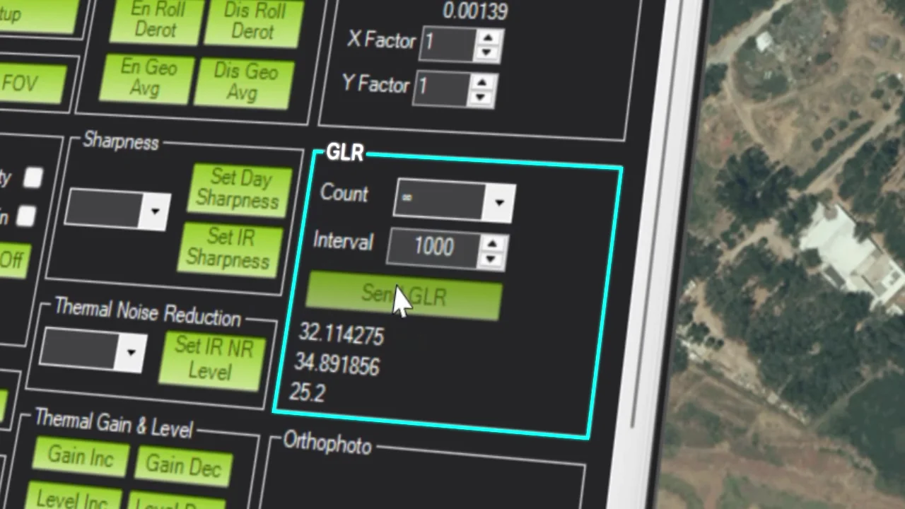
Most airborne geolocation workflows rely on line-of-sight projection. The system combines platform GPS position, altitude, attitude, heading, gimbal angles, and sensor orientation to estimate where the center of the video frame intersects the ground.
In theory, this creates a direct geometric link between the image and the map. In practice, every one of these inputs carries a tolerance. When those tolerances compound – and when the line of sight extends over hundreds or thousands of meters – the result is a coordinate offset that no amount of image stabilization can eliminate.
This article describes the sources of that offset, the geometry that amplifies it with range, and the image-based approach that Ground Location Refinement (GLR) uses to correct it in real time.
Line-of-sight projection
Standard airborne geolocation derives ground coordinates by projecting a ray from the sensor origin through the center of the video frame and intersecting it with a terrain model. The inputs to that projection are:
| Input | What it measures | How it introduces error |
|---|---|---|
| GPS / INS | Platform position | Small drift shifts the entire projection |
| Attitude (INS/IMU) | Roll, pitch, yaw | Any tilt tilts the line of sight with it |
| Gimbal angles | Where the camera is pointing | Reported angle and actual angle always differ slightly |
| Boresight alignment | Camera-to-gimbal offset | Drifts over time – vibration and maintenance shift it silently |
| Slant range | Distance to ground | The further away, the more any error gets amplified |
Any one of these errors, on its own, can be enough to produce a significant coordinate offset. They do not need to compound. In practice, several are always present.
Angular error and range amplification
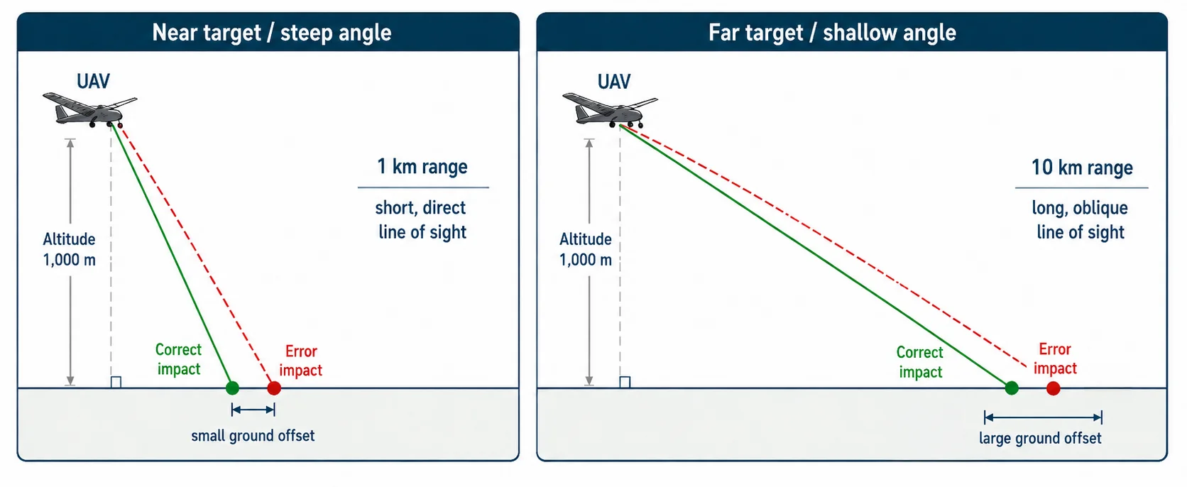
The further away the target, the shallower the angle at which the line of sight meets the ground. At low depression angles, even a small angular deviation produces a large displacement on the ground – because the line of sight is nearly parallel to the surface it is intersecting.
The effect compounds with range. A sensor looking at a target 1 km away at a steep angle has a short, direct line of sight. The same sensor looking at a target 10 km away at a shallow angle has a long, oblique one – and any error in pointing direction gets amplified accordingly.
Stop calculating. Start matching.
Instead of relying solely on projection-derived coordinates, GLR compares the live EO/IR video frame against geo-referenced orthophoto data.
Ground Location Refinement – how it works
What the system does
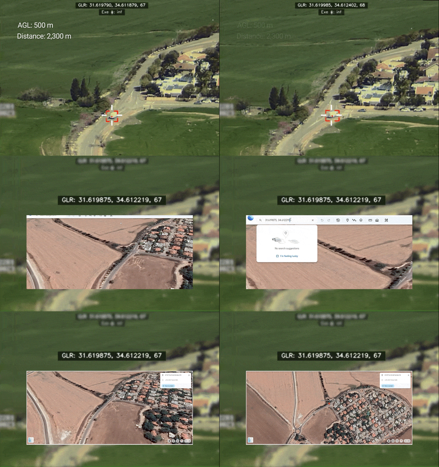
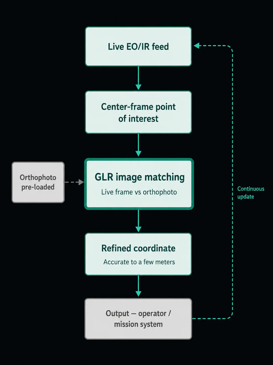
GLR starts with a live electro-optical or infrared feed. The crosshair marks a point of interest at the center of the frame. The system takes that frame and matches it against high-resolution orthophoto data covering the area.
By matching visual features between the live imagery and the known map – road edges, building corners, field boundaries, path intersections – the system can determine where the live frame actually aligns with the ground, and output a corrected coordinate accordingly.
Once the match is established, the system outputs a refined ground coordinate – accurate to within a few meters – continuously updated as the platform moves, the target moves, or both.
The system is not environment dependent. Matching operates across urban, rural, and mountainous terrain. In low-light or nighttime conditions, GLR functions using infrared imagery, applying the same matching process to thermal sensor output.
GLR within the TRIP ecosystem
GLR does not operate in isolation. Within the TRIP architecture, it works alongside two other image-intelligence capabilities – Object Tracking and Scene Tracking. Each addresses a different layer of the aerial observation problem.
Object Tracking
Keeps a selected target within the video frame as the platform or target moves.
Scene Tracking
Maintains visual lock on a defined area of ground across platform maneuver.
GLR
Takes whatever is at the center of the frame and produces a precise, continuously updated ground coordinate.
The result is a system that does not just show you a target. It shows you a target, holds it in frame, and reports its location – continuously, regardless of whether the platform moves, the target moves, or both.
Operational scenarios
What these scenarios share is not the environment, the platform, or the mission type. It is the moment when someone has to act on a coordinate – and needs to know it is right.
Urban ISR
Dense environments where building edges and road intersections give GLR abundant features to match against.
Border surveillance
Long slant range, targets moving along a fence line, and continuous operation require coordinate confidence across the entire sortie.
Search and rescue
When a ground team needs to reach a specific location fast, the coordinate passed from the aerial asset needs to be exact.
Night operations
Matching against orthophoto in infrared is more challenging than in daylight, but GLR applies the same matching process to thermal sensor output.
Infrastructure inspection
Video observations need to be convertible to actionable coordinates for post-mission reporting and follow-up.
Summary
Stabilized video solves one problem: it lets you see clearly from a moving platform.
It does not solve the other problem – knowing exactly where what you are seeing is located on the ground.
That gap exists because of the way airborne geolocation works. Every input to the coordinate calculation carries a tolerance. At distance, those tolerances grow. And none of it is visible in the video feed. The image looks clean whether the coordinate is accurate or not.
Ground Location Refinement addresses this gap by replacing the projection estimate with an image-derived one. By matching live EO/IR imagery against geo-referenced orthophoto data, GLR produces a refined ground coordinate that is independent of the upstream error sources and robust across environments, sensor modes, and ranges.
A coordinate is not just a number. It is a decision.